Smart Electrical Panel Protection and Emergency Alert System
An embedded system that watches an electrical panel for heat, smoke, gas and flame, then responds in stages: cooling, an alarm, disconnecting the load and an SMS to a responsible person.
Debugged on a breadboard, then built on a soldered PCB. Six test scenarios passed under simulated hazard conditions.
The relay disconnected the load within one 2-second polling cycle of an emergency, and SMS alerts were delivered.
Gas readings are raw values, not calibrated concentrations. Not tested inside a real panel.
Problem
Electrical panels are a common starting point for fires caused by overheating connections, insulation breakdown or short circuits. These faults can develop long before anyone notices. Automatic monitoring lets a hazard be contained within seconds and lets a responsible person be told even when nobody is on site.
System
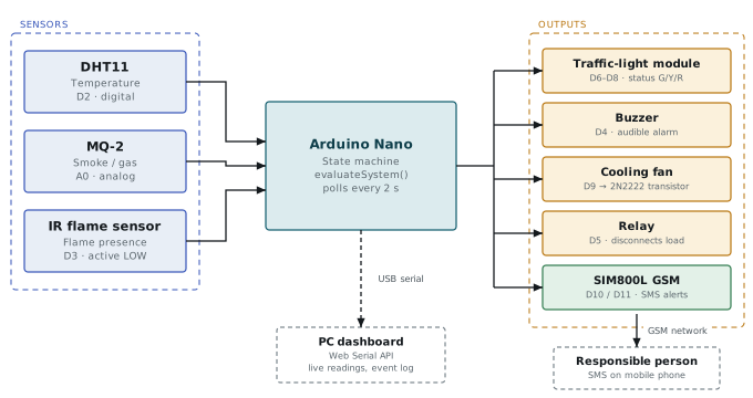
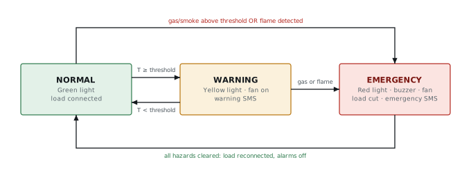
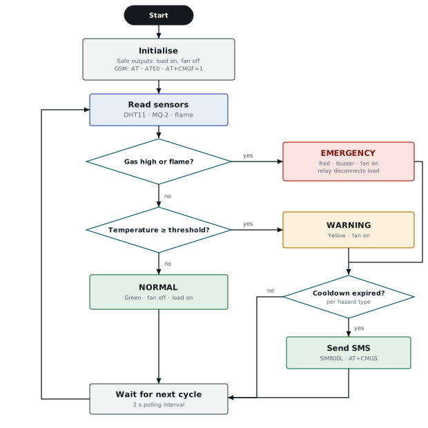
Three sensors feed the Arduino Nano, which evaluates them every two seconds and drives a three-state machine. Flame and gas are separate alert sources with their own SMS cooldown, so one hazard can never silence a notification about another.
| State | Trigger | Response |
|---|---|---|
| Normal | All readings in range | Green light; load connected |
| Warning | Temperature above threshold | Yellow light; fan on; warning SMS |
| Emergency | Smoke or gas high, or flame | Red light; buzzer; fan; load disconnected; emergency SMS |
Hardware
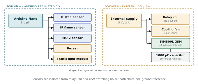
Two isolated power domains keep actuator switching from corrupting sensor readings. The Nano’s regulated 5 V rail powers the sensors, buzzer and lights; a separate 5 V / 2 A supply powers the relay, fan and SIM800L, whose transmit bursts draw about 2 A. A 1000 µF capacitor near the SIM800L absorbs those spikes.

Firmware
All outputs are driven from one sensor snapshot per cycle, and the relay and fan return to a safe default on every reset, so a reset never leaves the panel unprotected. Two bugs were found and fixed: the AVR snprintf() cannot format floats, so temperatures are converted with dtostrf(); and the SMS cooldown blocked any alert in the first 60 seconds after boot until the timer was initialised to a time in the past.
Testing
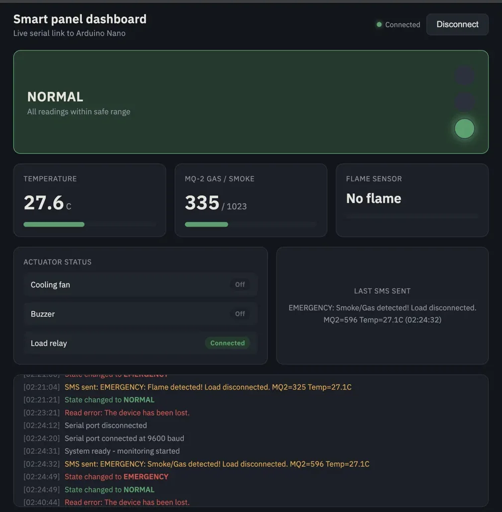
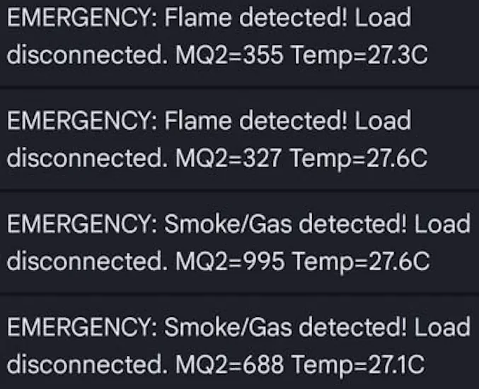
Six scenarios were tested: power-on self-check, GSM registration, temperature warning, gas/smoke emergency, flame emergency and automatic recovery. A browser dashboard using the Web Serial API showed live readings and the state log during the tests.
Results and limits
Shown
- Correct state transitions in all trials
- Load disconnected within one 2 s cycle
- A false flame trigger traced to relay noise and fixed by separating power rails
Limits and next steps
- MQ-2 needs on-site threshold calibration; readings drift with warm-up and humidity
- SMS delay depends on the GSM network, from seconds to under a minute
- Next: calibrated gas readings, per-circuit isolation, local logging
Resources
- PDF Project report · 12 pagesAAQ-P05_Smart-Panel-Protection_Project-Report.pdf Open PDF